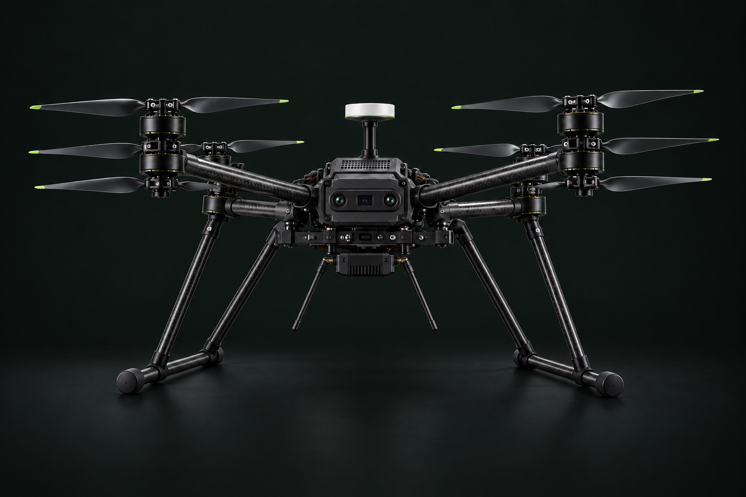
Sky-facing GNSS
Position and timing from a separate top pod. Preserve the sky view and evaluate interference from radios and propulsion electronics.
Positioning pathTHE AIRCRAFT / STACKED X8
An eight-rotor platform concept built around four coaxial pairs. A focused approach to propulsion, system integration, and the next stage of aerial engineering.
CONCEPT / IN DEVELOPMENTPayload, endurance and the operating envelope remain to be established through measurement and testing.
ONBOARD INTEGRATION
Explore the proposed module locations. Numbered markers link to the integration notes below.
Position and timing from a separate top pod. Preserve the sky view and evaluate interference from radios and propulsion electronics.
Positioning pathCentral mounting for controllers and proposed companion compute. Account for vibration, cooling, cable routing, and each bank’s independent power path.
Control architectureThe visible front module illustrates two camera lenses and a central depth-sensor window. Final sensor selection, calibration, interfaces, and mounting remain to be defined.
Perception integrationAn underside radio enclosure with external stick antennas illustrates the intended drone-to-drone mesh and ground-control links. Antenna clearance, spacing, and coverage require validation.
Communications integrationCOMMUNICATION MESH / PROPOSED
Each aircraft carries its own communication module and stick antennas. The intended network supports peer messages and a ground-control link.
Peer-to-peer mesh links
Ground controlDirect or via a configured peer relay
Exchange aircraft status and mission messages. Mesh routing would select a peer path when direct communication is unavailable.
Use a direct link when available, with a configured drone relay as a proposed alternative. Ground command authority remains explicit.
Attitude control stays local. Loss of peers or ground connectivity must invoke defined onboard behaviour.
Network concept only. Radio selection, routing, security, latency, and moving-aircraft tests are pending; no range or self-healing performance is claimed.
THE BASELINE
The architecture defines the research direction. Qualification establishes what the aircraft can deliver.
Eight rotors at four arm positions. Upper and lower rotor interaction is a core part of propulsion testing.
Each bank includes one motor per arm, balanced rotation directions, and its own power and control path.
The revised concept shows sky-facing GNSS, a front perception module, and a communication enclosure with stick antennas. Final hardware remains under review.
PLATFORM AT A GLANCE
| Design area | Current direction | Status |
|---|---|---|
| Rotor layout | Four coaxial pairs / eight motors | Selected baseline |
| Normal operation | All eight motors operating | Development baseline |
| Control and power | Two independently powered four-motor banks | Proposed architecture |
| Navigation and links | Separate GNSS, perception, and proposed mesh / ground-control links | Integration concept |
| Payload and endurance | To be established with a defined mission and reserve | Not yet qualified |
| Bank-out behaviour | Controlled-landing envelope and transition testing | Requires validation |
THE DEVELOPMENT PATH
Weigh assemblies and measure isolated-rotor and coaxial-pair behaviour.
Evaluate structure, power distribution, sensors, and control allocation together.
Test timing, disagreement, and fault transitions in controlled environments.
Build a measured operating envelope through restrained and incremental flight tests.
WHAT COMES NEXT
Start with your payload, environment, and desired outcome.